Sunday, March 19, 2017

3/16 Nodal Analysis

We started the class with a problem, and we used nodal analysis to solve it which give us the equation in the picture below:

To solve equation, we need to do a calculation with lots of unknowns.
At the end of this class, we will learn another way to solve this question but with fewer unknowns. The method is called Mesh Analysis.

We did a lab to make sure that the nodal analysis work.

Nodal Analysis

1.
In pre-lab, we predicted the voltage V1 and V2
The picture below is the calculation of determining V1 and V2

From the picture, we got V1=2.424 V  and V2=4.424 V
Equipment:
1. breadboard
2. some wires
3. voltmeter
4. resistors with resistance 6.8k, 10k, and 22k ohms
5. Analog discovery

2.

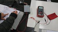
The picture above is the basic set up for this lab.
After we connected everything correctly, we measured the voltage across 6.8k ohms resistor and 22k ohms resistor.
We got V1 (measured) =  2.37 V
            V2 (measured) = 4.34 V (the pictures below)

3.
We calculated the % error from what we got, and we got:
 
% error for V1 = 2.07%
% error for V2 = 1.81%
From this lab, we can know that nodal analysis is ok to use.

After this lab, we learned a new method to analyze the circuit which is called mesh analysis.

The picture above is a simple set up of mesh analysis.
In the mesh analysis of a circuit with n meshes, we take the following three steps. 1. Assign mesh currents i1, i2, . . . , in to the n meshes.
2. Apply KVL to each of the n meshes. Use Ohm’s law to express the voltages in terms of the mesh currents.
3. Solve the resulting n simultaneous equations to get the mesh currents.
(from Day 5 Notes Nodal and Mesh Analysisc.pdf)

And we did another example with current source in it

The problem involves the usage of supermesh
A supermesh results when two meshes have a (dependent or independent) current source in common.
(from MESH ANALYSIS WITH CURRENT SOURCES.pdf)
For this problem, we ended up with the answer:
i1=-1.3333
i2=-3.0667
i3=-0.0667
Therefore i0=i2-i3=-1.7333A

Summary
The lab we did today is to make sure that the nodal analysis work, and the result of the lab actually prove that the nodal analysis works but it is hard to do it by hand. Therefore, we leaned a new method to analyze the circuit which is called "Mesh Analysis". This method can make the problem much easier to calculate which means fewer unknowns. The number of meshes would be the same number of unknowns.

Sunday, March 12, 2017

3/9 Temperature Measurement System


The picture is the quiz we had in the beginning of the class.
The way we solved it is shown in the picture, and this method will be changed later in this post.

Temperature Measurement System


To do this lab, we need to find a value for R in the circuit above such that Vout changes by at least 0.5V over the specified temperature difference.

Through these two pictures, we found R should be a value between 4367 ohms and 17633 ohms. Our group pick R to be 10K ohms.
According to the circuit in the lab manual, we had the lab set up in the picture below:

Equipment:
1. breadboard
2. some wires
3. voltmeter
4. Thermistors
5. 10K ohms resistor


From the data above, the measured thermistor resistance at room temperature is 9.9k ohms and body temperature is 5.9k ohms.
The actual resistance of 10k ohms resistor is 9.8k ohms
We measured the voltage across the resistor  at room temperature = 2.46V
                       the voltage across the resistor at  body temperature = 3.09V
We plugged the measured thermistor resistance into the equation, and we got Vout changes = 0.6337V (calculated)
The actual Vout changes = 3.09 - 2.46 = 0.63V (measured)
The %error we got is about 0.58%, which is very close to what we expect.
The video below is how we found the Vout changes:


This question is the same the quiz we had in the beginning of the class but using a different method called Nodal Analysis (Node Voltage Method).
Steps to determine Node Voltages:
1. Select a node as the reference node(ground). Assign all the others node v1, v2, ....
2. Apply KCL to each node but without reference node.
3. Use Ohm's Law to express the branch currents in terms of node voltages
4. Solve the equations
(from Day 4 Notes Nodal Analysis )
We can see that it is much easier than the way we did in the beginning of the class.

The next example is nodal analysis with voltage sources.

Basically, it is the same as what we did in the last example. The only difference is we had "supernode" this time.
The definition of supernode: A supernode is formed by enclosing a (dependent or independent) voltage source connected between two nonreference nodes and any elements connected in parallel with it.(from Day 4 Notes Nodal Analysis)
In the picture, we treated v2 and vx as a supernode, which will make this problem much easier compared to doing this problem with the method we did before this class.

Summary
We learned a different method (Nodal Analysis) to solve the problems with resistors and voltage sources in them. This method will at least make the problems 50% easier than before. Because the less unknowns we have, the easier the problems are. For the lab, we learned how to create a circuit that can produce different Vout depending on the temperature that the thermistor is. This circuit can be used in real life, like circuit protection and volume control.

3/7 Dusk-to-Dawn Light


We were asked to predict the result if we attached a hotdog to a line cord and apply a 120 V potential across it.
The answer is the hotdog will slowly cook.
And then, we were asked to predict what will happen if we insert LEDs into the hotdog both parallel and perpendicular to the hotdog axis.
The answer is the LEDS parallel to the hotdog will light.


From the circuit above, find v0 and i0 in the circuit
We did in the white board, and we got:

v0 = 8V, i0=4A


From the picture above, we leaned how to create a Vout that we want by using different value of resistance in the circuit.

Dusk-to-Dawn Light

The picture above is the basic set up for this lab.
Equipment:
1. breadboard
2. photocell
3. resistor
4. Bipolar Junction Transistors (BJTs)
5. some wires
6. MOSFET
7. LED
8. voltmeter


1.
We applied KVL around the outer loop of the circuit to determine the voltage VB for photocell resistances of 5K and 20K.
We got for resistance of 5K, VB is equal to 1.67V
            for resistance of 20K, VB is equal to 3.33V
2.

The measured value of VB for photocell resistances of 5K ohms and 20K ohms are shown in the picture.
Compared to calculated value of VB, when it was under light, the difference is about 76%. When it was covered, the difference is about 42%.
The reason why the difference is so big is because the value of resistance for photocell is not 5K ohms and 20K ohms. It is 0.9K ohms and 10K ohms, which will give us a big difference.
3.


Summary
We discussed some example about dependent source, series resistors and voltage division, parallel resistors and current division, and we did one experiment--Dusk-to-Dawn Light. From all this practices, we had a clear idea about how resistors work in a circuit, and also, we knew how to create a Dusk-to-Dawn Light now!!

3/2 Resistors and Ohms Law & Dependent Sources and MOSFETs


We were given a circuit above and were asked to determine the number of branches, loops and nodes in the circuit.
First, we didn't count the nodes between the current source and the resistor, so we came up with different answer.
There are 5 nodes and 7 branches, according to the fundamental theorem of network topology:
b = L + N − 1
We got 3 independent loops in this circuit.

Given the circuit above
Find I and Vab in the circuit
By applying KVL to the loop, we got I = 4A, and Vab = 28V.

We did two labs.
One is Resistors and Ohms Law - Voltage-Current Characteristics
Another one is Dependent Sources and MOSFETs

Resistors and Ohms Law - Voltage-Current Characteristics

The resistor we used in this lab, and the resistance value of this resistor is 98.2 ohms.
The data we got by changing the voltage 
Because the voltage source only has 5 different voltage options, there are only five different data.
From the graph, we can that the measured resistance value of the resistor is 97.78 ohms.

Dependent Sources and MOSFETs

We used the same resistor which the resistance value is 98.2 ohms.
The photos above are the basic set up for this lab.
The table and the graph above can help us determine the threshold voltage.
From the table and the graph above, the threshold voltage is around 0.69 V.
The transistor is behaving like VCCS (Voltage Controlled Current Source).

Now we only consider the data from 0.66 to 0.78.
From the graph above, we used a best fit line to determine the value of g for circuit, and the value g is 349.93.

Summary
We learned the fundamental theorem of network topology, KVL, KCL, and how to use MOSFETs today by doing some of the examples in the class and doing two labs to make sure that we know how to use Waveform Generator. Although our group didn't finish the lab in the class, we did it on Friday. After struggling to figure out how to produce two voltage source, we finished the lab very quickly.

Wednesday, March 1, 2017

2/28 Solderless Breadboards, Open-circuits and Short-circuits


This is the basic set up of this lab.
Equipment:
1. breadboard
2. use of digital multimeters (DMMs) to measure resistance
3. some wires


Connect the leads of the DMM to two holes in the same row on the breadboard
The value of the DMM is 0.8. Closed circuit.


Connect two rows of holes on opposite sides of the central channel of the breadboard
The value of the DMM is infinite. Open circuit.


Connect two arbitrary holes (not in the same row) of the breadboard
The value of the DMM is infinite. Open circuit.


Use a jumper wire to connect two different rows on the breadboard
Closed circuit
The value of the DMM is 1.1. Closed circuit.

Summary
This purpose of this lab is to be familiar with using breadboard and DMM.
By connecting different holes on the breadboard, we can see that only two holes in the same row on the breadboard, or using a jumper wire to connect two different rows on the breadboard can be made as a closed circuit.