The picture below is what the operational amplifier based schmitt trigger looks like:

Next, we introduced the non-symmetrical schmitt trigger.
The picture below is what the the non-symmetrical schmitt trigger looks like.

Then, we talked about the step response of a series and parallel RLC circuit.
Review questions:


Next, we did lab.
RLC Circuit Response
Pre-lab

The picture is the differential equation relating Vin and Vout for the system.
By using the equation, we can determine the damping ratio and natural frequency of the circuit.

The damping ratio is 1563.8 and natural frequency is 10105.8Hz.
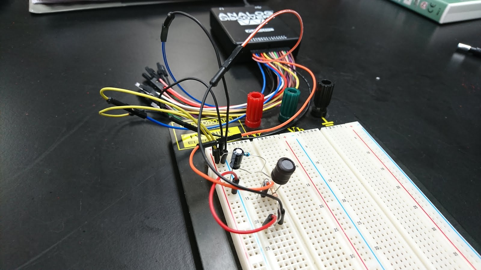
The picture below is the basic set up for this lab.
Result:

The damping ratio from the graph is 0.25, rise time is 2.15*10^-4, DC gain is 8.
After lab, we talked more about the second order circuits.
Summary
We learned about what the Schmitt Trigger is, and reviewed about RLC circuit which is second order circuit. In order to recover the transmitted analog
signal, the output is smoothed by letting it pass through a “smoothing” circuit, as illustrated at right. An RLC circuit may be used as the smoothing circuit.
No comments:
Post a Comment